Creating a Custom HM-11 Breakout Board
After successfully creating a working HM-10 module I found that my project would benefit from a smaller form factor bluetooth module. After some research I found that there was a newer less documented HM module, the HM-11. Looking online I couldn’t find any guides or breakouts for this module except the quite pricey BLEBee (£30~). I decided therefore to create my own custom breakout.
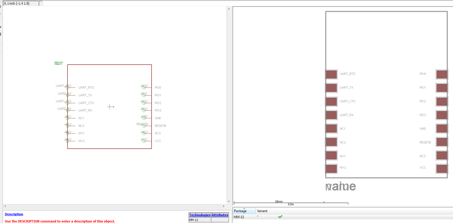
To design the breakout I used Eagle PCB. This software allows you to design various circuits and custom board layouts. To learn how to use the software I followed the following online guide. This guide shows you how to create a schematic for your project. The schematic is the first part to the process, it defines the links between components and the components themselves. Whilst creating the schematic I realised that I was missing a key component to the breakout, the HM-11 module. Therefore my next step was to create a custom HM-11 library for Eagle. To create a library I followed an online guide which describes the steps clearly. Creating the library meant that I needed to understand the ports of the HM-11 module, these were described in the online wiki for the module. This is what the custom library looked like after completion:
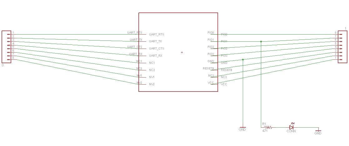
Once I had the HM-11 library I was then able to add it to my project and wire it up in the schematic. In my breakout I added a status led so that it would aid debugging. Everything else was simply wired to the breakout ports:
Once the schematic had been created and wired up correctly the next step was the create the ‘device’. The device is the final board that will be printed and requires you to place and route the components. When routing components you can select which side of the board they will be on and where the wires will be placed. For example, I placed the resistor on the back of the board for the status led and the led itself on the front of the board. To do this you can select a hole where the wire passes through from the front of the board to the back. This allows you to take advantage of both sides for more components or a cleaner layout. Here is the final device:
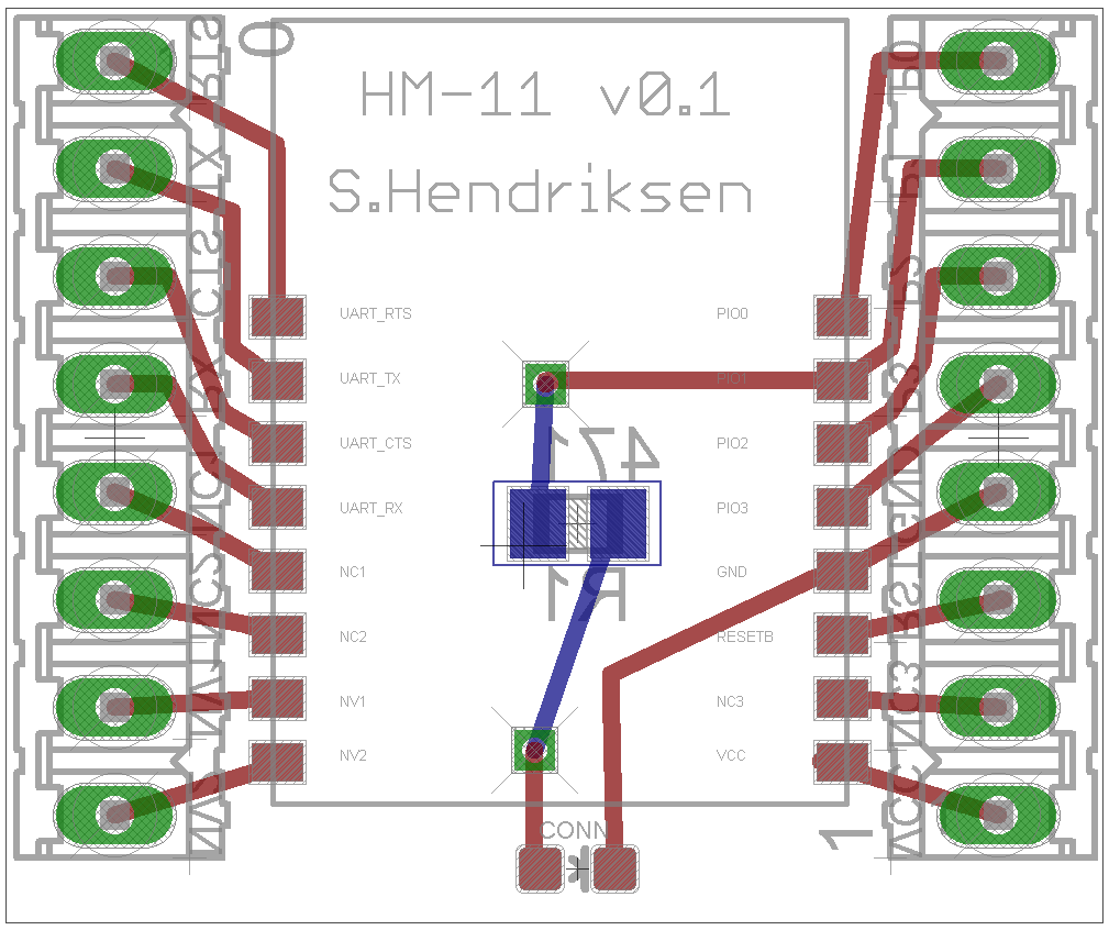
The blue wires are on the back of the board and the red wires are on the front.
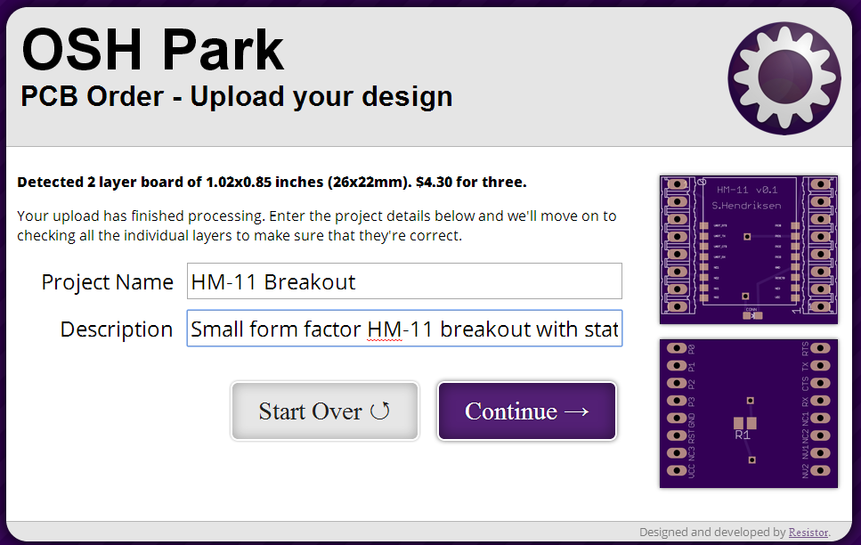
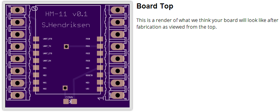
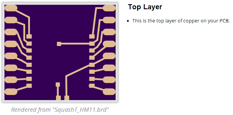
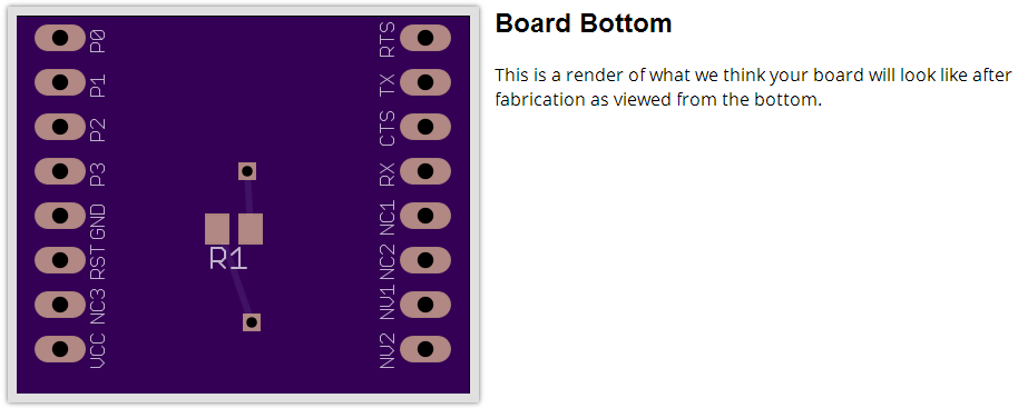
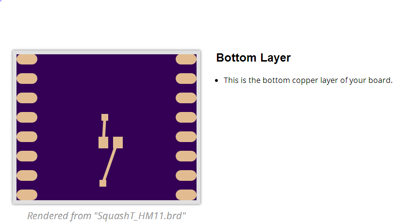
The next step was to get the board printed! To print the board I used OSHPark. On the site you can upload your .brd file and it will generate the print. You can then review the board before you order a multiple of three boards. Here are some of the review images of the board:
The board usually takes a couple of weeks to be printed and shipped. I’ll update this post once I get the boards.
UPDATE (06/09/14):
The modules and my custom breakout boards have arrived!
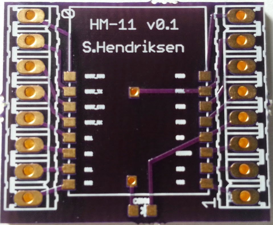
Front of breakout:
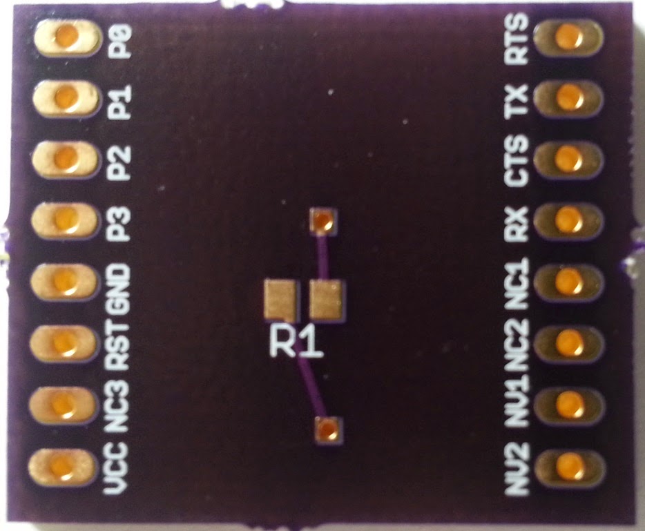
Back of breakout:
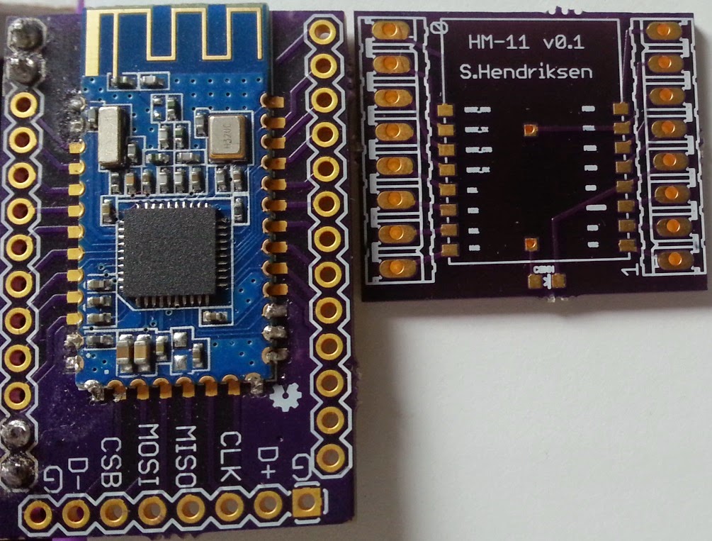
Board size comparison (HM-10 breakout left - HM-11 breakout right):
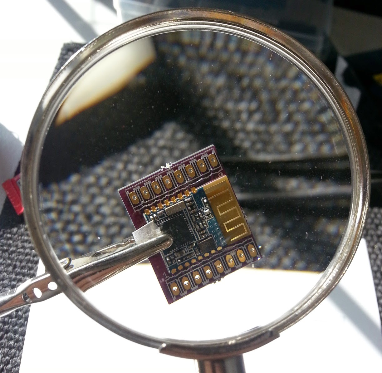
Clipping the HM-11 module to the breakout to help with the soldering:
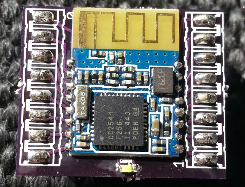
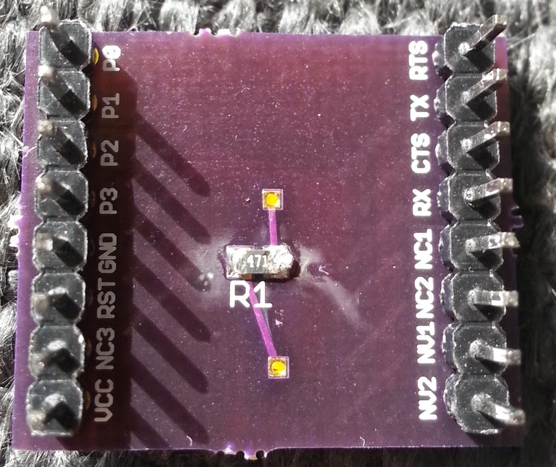
Complete board after soldering;
Front:
Back:
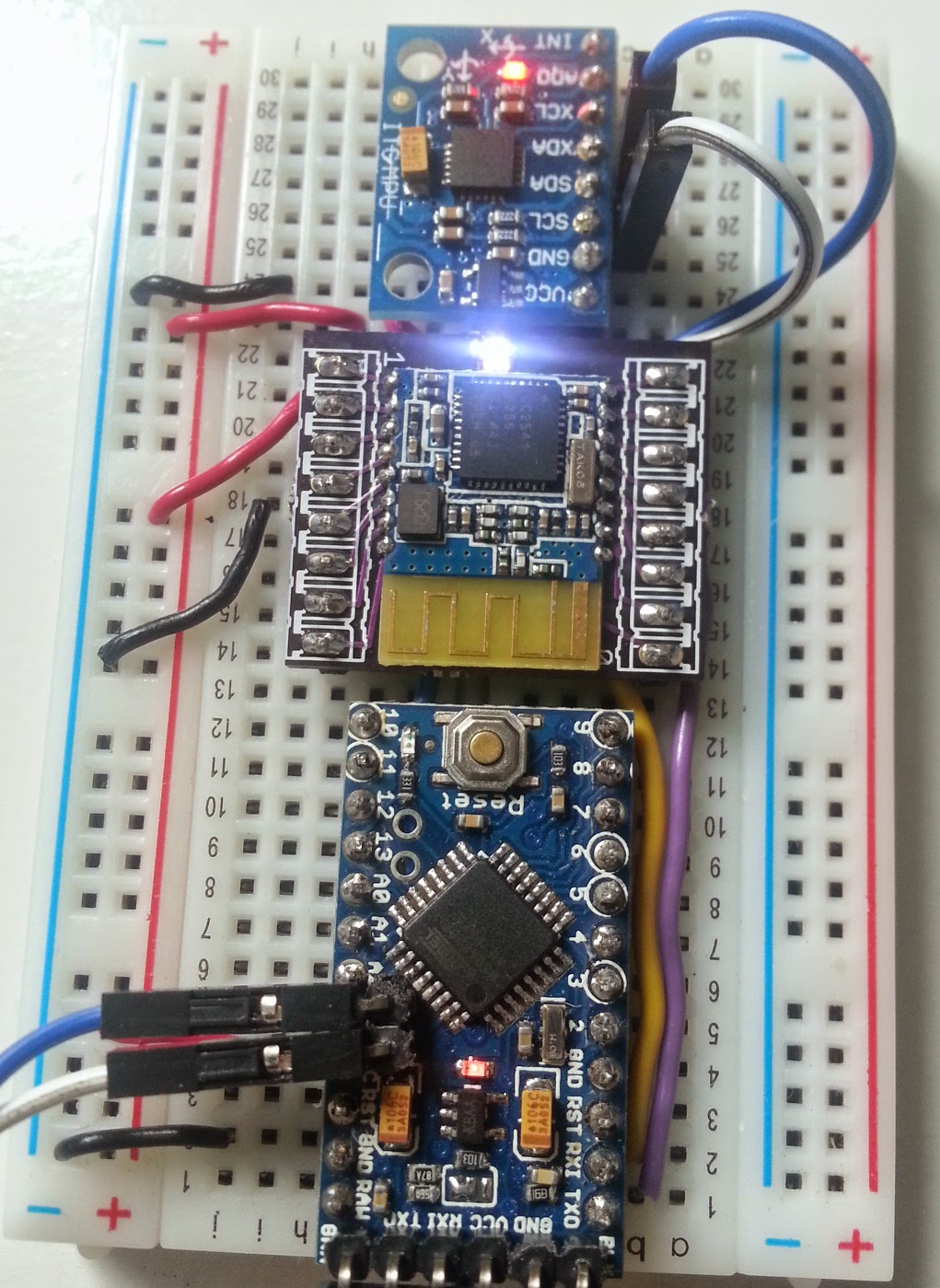
After soldering the module I checked the connections and then plugged it straight into my existing breaboard setup, it worked straight away!
Setup (Arduino pro mini, Custom HM-11 and MPU6050):