Building a BLE (Bluetooth Low Energy) Breakout Board
The first area I have started to look at for my final year project has been the communications side. Without resolving the wireless communications my project would not be able to proceed.
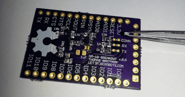
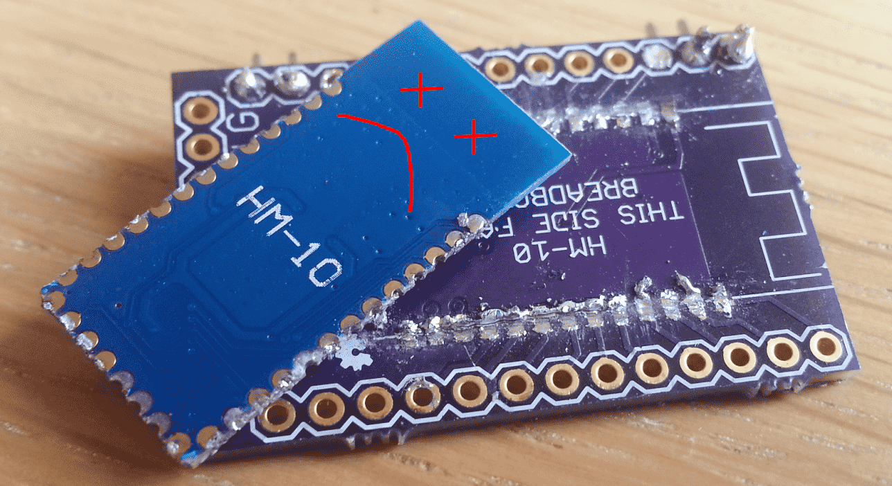
To be able to communicate over BLE with my Arduino I’ve followed an online guide for the module: HM-10. The guide has been very useful and has allowed me to produce a module that will aid with development and debugging. When data is received or transmitted from the module it will flash a series of LEDs. This will allow me to understand the data flow when testing later on.
Creating the HM-10 breakout has been very challenging. My first attempt at creating the breakout caused strange results and in the end the module burnt out. This was mainly due to my rusty soldering skills. Aftermath:
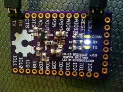
My second attempt proved far more successful but also required a lot more understanding of the components. When I first soldered all the components to the board I found that the device was not receiving or transmitting. The Bluetooth itself worked fine as I was able to see the device on my phone and connect to it, which caused the connection LED to go solid. The problem was that I did not get a response from the module and the RX/TX LEDs were not blinking when data was sent. My only step from here was to debug the module using a multi-meter.
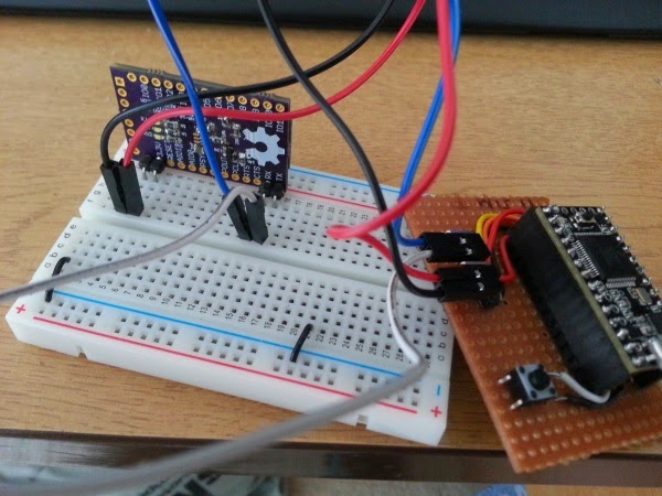
The first problem was the fact that the FTDI cable I was using was not working as thought it would. The cable mentions that it runs at 3.3v which is the maximum power the module should be running at. When I put the multi-meter to the cable though it showed that it was actually running at 5v!! After some research and reading of the data sheet I found that the RX/TX lines run at 3.3v but the main power source runs at 5v. Luckily I’ve found that my second HM-10 module is a lot tougher than the first and was still functioning. Just when I thought I learnt my lesson the first time I then used the Teensy 3.0 to power the module as I found from the description that it runs at 3.3v. My problem this time was that I connected the module straight to the VCC power line.. which is 5v again! Luckily the module seems to be able to withstand 5v.. at least from the accidental testing I did on it. After this I corrected the connections and was finally running the module on 3.3v.
The second problem was an error with the breakout board. The RX LED was always on until I connected the RX line, which is the opposite of how it should work. After seeing this I opened up the schematic for the breakout and found that the RX and TX labels printed on the breakout were the wrong way around, so visually I needed to connect the RX-RX and TX-TX, although technically this was really RX-TX, as it should be.
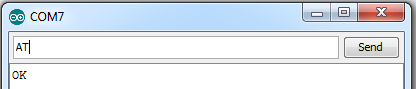
Finally the last problem was a faulty LED, after I went through each LED and gave it current i found that the last TX LED was not working. I replaced this LED and then connected the module to Realterm. The module was then responding to commands and is now set-up for future development! The below image shows me sending the command “AT” (test connection command) and getting the response “OK”!
Further images of the setup: